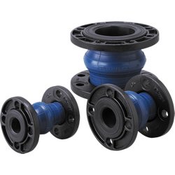
 High Performance Single-Sphere Flexible
Rubber Joint
• Unique spherical shape
• Outstanding pressure-resistance performance
• Unified face-to-face dimension
Application
Vibration absorption of pumps and equipment, absorption of piping eccentricity, expansion and compression
Installation
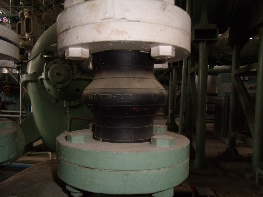
Pumps, chillers, receiving tanks, high-set water tanks, etc.
Specifications
| Nominal diameter: | 20A – 400A |
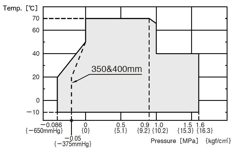
| Maximum working pressure: | 1.0MPa(10.2kgf/cm²) |
| Operating temperature: | -10°C – 70°C |
| Expansion and compression eccentricity: | 10 – 25mm |
| Feature |
| Achievements Having been used in more than 20 countries for over 30 years, TOZEN brand products proudly demonstrate their popularity. Reliability Unparalleled durability is guaranteed by the distinctive and strict design standards of TOZEN. Quality Manufactured in TOZEN’s own factory under thorough control with ISO9001 quality management system. |
| Applications |
| ● This product is mainly applicable for air conditioner, water supply and drainage, and sanitation facilities around piping systems in commercial and industrial buildings and plants. ● Applicable fluids are exclusively water including cold water, warm water, cooled water, and seawater, etc. ● This product cannot be used for pool water, oil, or boiled water. |
| Operating Conditions and Performance |

● Bursting Pressure: |
| Dimensions and Allowable Movements | ||||||||||||
| Nominal Dia. | Dimension [mm] | Mass [Kg] |
Allowable Movement [mm] | Installation Tolerances [mm] | ||||||||
| mm | inch | L | φd | T.M | A.E | A.C. | A.M. | T.M | A.E | A.C. | A.M. | |
| 20 | 3/4 | 140 | 25 | 1.1 | 10 | 5 | 10 | 15° | 4 | 3 | 6 | 7.5° |
| 25 | 1 | 140 | 25 | 1.6 | 10 | 5 | 10 | 15° | 4 | 3 | 6 | 7.5° |
| 32 | 1 1/4 | 150 | 40 | 2.0 | 20 | 10 | 20 | 15° | 8 | 3 | 6 | 7.5° |
| 40 | 1 1/2 | 150 | 40 | 2.1 | 20 | 10 | 20 | 15° | 8 | 3 | 6 | 7.5° |
| 50 | 2 | 150 | 50 | 2.7 | 20 | 10 | 20 | 15° | 8 | 3 | 6 | 7.5° |
| 65 | 2 1/2 | 150 | 65 | 3.7 | 20 | 10 | 20 | 15° | 8 | 3 | 6 | 7.5° |
| 80 | 3 | 150 | 75 | 3.8 | 20 | 10 | 20 | 15° | 8 | 3 | 6 | 7.5° |
| 100 | 4 | 150 | 100 | 4.6 | 20 | 15 | 20 | 15° | 8 | 3 | 6 | 7.5° |
| 125 | 5 | 150 | 125 | 6.6 | 20 | 15 | 20 | 15° | 8 | 3 | 6 | 7.5° |
| 150 | 6 | 150 | 150 | 9.1 | 20 | 8 | 15 | 15° | 8 | 3 | 6 | 7.5° |
| 200 | 8 | 150 | 200 | 12 | 20 | 8 | 15 | 15° | 10 | 3 | 6 | 7.5° |
| 250 | 10 | 200 | 250 | 20 | 25 | 15 | 20 | 15° | 10 | 3 | 6 | 7.5° |
| 300 | 12 | 200 | 300 | 22 | 25 | 15 | 20 | 15° | 10 | 3 | 6 | 7.5° |
| 350 | 14 | 200 | 350 | 30 | 25 | 15 | 20 | 15° | 10 | 3 | 6 | 7.5° |
| 400 | 16 | 200 | 400 | 42 | 25 | 15 | 20 | 15° | 10 | 3 | 6 | 7.5° |
● Flanges with mild steel and ductile iron in JIS10K, ANSI150, PN16 are standard.For other flanges, please consult us.
● Flange material can be changed to SUS304 and SUS316.
● ANSI flange type for 20&32mm is not produced.
● The flange material for ANSI150 25mm and PN16 20&25mm is mild steel only.
● The flange material for 350&400mm is mild steel only.
● Like the drawing on left, the inner rubber for 20&25mm is flat type.
● For 32 ~ 300mm, the inner rubber flat type is also possible.
・A.C.: Axial Compression, A.E.: Axial Elongation, A.M.: Angular Movement, T.M.: Transverse Movement.
・Mass indicates only the case with JIS 10K (Ductile Iron) flanges. However,mass for 350&400mm is with JIS 10K(Mild Steel)flange.
・Tolerances for installation are included in the allowable movements (Allowable movements = Tolerances for installation + Operating movements).
・Please note that the information in the above table is for single movement only.
In case of complex movements, please do adjustment by using the following formula.
C.A.E. (C.A.C.) = A.A.E.(A.A.C.) × {1-(T.M./A.T.M+A.M./A.A.M)}
C.A.E. (C.A.C.): Correct Elongation Movement (Correct Compression Movement)
A.A.E. (A.A.C.): Allowable Elongation Movement (Allowable Compression Movement)
A.T.M.: Allowable Transverse Movement
A.A.M.: Allowable Angular Movement
Example: In case of 100mm joint, if 10mm transverse movement is needed,
then the correct elongation should be: C.A.E = 15 × {1- (10/20+0/15)} = 7.5mm
・There is reaction force from rubber joints due to the load of the internal pressure, so during the installation, please use the metal fittings to fix the pipe tightly to ensure the joints work efficiently. In case the pipe cannot be fixed tightly, please use the control unit for the joints.
ポンプ吸込側取付けに関する注意事項
●ポンプ設置位置より低い水槽からの汲み上げライン、及び常時負圧が生じるラインでは、不具合が発生する場合があります。上記ラインには、タフボーイ又は、LSコネクタ(サクション用)のご使用を推奨します。

Note:The contents of this catalogue are subject to change without notice.

