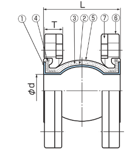
Dimensions
| Nominal Dia. | [Dimension mm.] | Mass [KG] | Allowable Movement [mm] | Installation Tolerances [mm] | |||||||||
|---|---|---|---|---|---|---|---|---|---|---|---|---|---|
| mm | inch | L | Ød | T | Eccentricity | Elongation | Compression | Deflection angle | Eccentricity | Elongation | Compression | Deflection angle | |
| 20 | 3/4 | 74 | 25 | 23 | 2.0 | 10 | 10 | 10 | 10 ̊ | 4 | 3 | 3 | 5 ̊ |
| 25 | 1 | 74 | 25 | 23 | 3.5 | 10 | 10 | 10 | 10 ̊ | 4 | 3 | 3 | 5 ̊ |
| 32 | 1 1⁄4 | 74 | 40 | 25 | 3.9 | 10 | 10 | 10 | 10 ̊ | 4 | 3 | 3 | 5 ̊ |
| 40 | 1 1⁄2 | 74 | 40 | 25 | 4.3 | 10 | 10 | 10 | 10 ̊ | 4 | 3 | 3 | 5 ̊ |
| 50 | 2 | 104 | 53 | 25 | 5.1 | 10 | 10 | 10 | 10 ̊ | 4 | 3 | 3 | 5 ̊ |
| 60 | 2 1⁄2 | 106 | 65 | 27 | 6.9 | 10 | 10 | 10 | 10 ̊ | 4 | 3 | 3 | 5 ̊ |
| 80 | 3 | 106 | 75 | 27 | 6.9 | 10 | 10 | 10 | 10 ̊ | 4 | 3 | 3 | 5 ̊ |
| 100 | 4 | 115 | 101 | 27 | 8.5 | 10 | 10 | 10 | 10 ̊ | 4 | 3 | 3 | 5 ̊ |
| 125 | 5 | 135 | 122 | 32 | 14 | 10 | 10 | 10 | 10 ̊ | 4 | 3 | 3 | 5 ̊ |
| 150 | 6 | 135 | 145 | 34 | 17 | 10 | 10 | 10 | 10 ̊ | 4 | 3 | 3 | 5 ̊ |
| 200 | 8 | 135 | 195 | 34 | 20 | 10 | 10 | 10 | 10 ̊ | 4 | 3 | 3 | 5 ̊ |
| 250 | 10 | 140 | 250 | 38 | 32 | 10 | 10 | 10 | 10 ̊ | 4 | 3 | 3 | 5 ̊ |
| 300 | 12 | 140 | 305 | 38 | 33 | 10 | 10 | 10 | 10 ̊ | 4 | 3 | 3 | 5 ̊ |
- Mass is the data when the material is SS400, and the flange is JIS10K.
- Use a joint within the range of allowable displacement.
-
Fixing allowable displacement = fixing time displacement + allowable
operational displacement. -
Each displacement in the chart is considered as single displacement,
so for multiple displacements, correction is necessary. Referring to
“Attention for handling or TOZEN HP”. -
Referring to “fixing bolt dimension table”, and use fixing bolt. Nut
is not necessary. (When companion flange is JIS 10K, material is
SS400, and when plain washer and gasket are not used.)