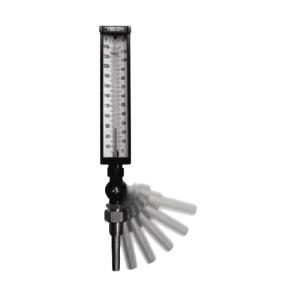
Liquid-in-glass Thermometers (VT & IT)
Liquid-in-glass thermometers have a glass tube in front of a metal scale. It extends into a metal chamber and has a glass bulb attached. This tube is completely sealed and the bulb contains a predetermined amount of liquid which, on expanding and contracting caused by temperature changes, will indicate the temperature for a given temperature range.
Installation of Liquid-in-glass Thermometers
NOTE: Make sure that while connecting the thermometer to the process, the sensitive portion of its stem (the last 2½” from the end) is located well within the flow of the medium being measured for temperature. This will ensure accurate readings with minimal response time.
Suggested Installation A
| Suggested Installation B
|
Accuracy
Inaccuracy may be caused by a broken tube, scale shifting in slots from original position, liquid separation, sensitive bulb not fully immersed in the media, or by poor circulation. Poor circulation can be explained as follows: If there is poor agitation in a fluid, the temperature stratifies or has hot or cold spots. The thermometer will read only the temperature in which the sensitive bulb is immersed. It is, therefore, important to locate on installation the sensitive bulb in the correct position.
Corrosion
The use of separate sockets of special material is recommended for corrosive or highly abrasive service.
Location
Care should be taken to locate the instrument on the equipment where vibration is at a minimum.
Thermowell Connection
Remove the thermowell from the thermometer if supplied with one. Install this thermowell in the pipeline or service as required. Insert the stem of the thermometer through the thermowell. Position thermometer for best reading position and tighten down. If the thermowells are purchased separately from the thermometers, then a suitable temperature transfer medium must be added to the well to properly conduct the temperature to the thermometer bulb. A mixture of graphite and oil, heat transfer paste, or even a light oil will suffice.
Union Bushing (Hub) Connection
Remove the union bushing from the thermometer if supplied with it. Install this union bushing in the pipeline or service as required. Insert the stem of the thermometer through the union bushing hole, engaging stem coupling nut with union bushing threads. Position thermometer for best reading position and tighten down coupling nut. 2½” minimum insertion.
- Sensitive Stem Immersion: The sensitive portion of the thermometer stem (the final 2½” from the tip) must be fully submerged within the flow path of the measured medium (e.g., cooling fluid). This ensures the sensing element (bulb) interacts directly with the fluid, eliminating measurement lag or inaccuracies from partial immersion.
- Pipe Size Alignment: For piping (e.g., 50mm diameter lines), this requirement typically corresponds to immersing a minimum of 50% of the pipe’s internal diameter (25mm for 50mm pipe) — but the 2½” sensitive stem immersion takes priority to maintain precision and recommended for better accuracy, even though condition each application may be varied.
In data center environments (where temperature stability directly impacts equipment reliability):
- Partial immersion of the sensitive stem, poor fluid circulation, or misalignment of the bulb with flow can cause stratification-related errors (e.g., reading only localized “hot/cold spots” instead of bulk fluid temperature).
While application conditions (e.g., pipe layout, flow rate) may vary, adhering to the 2½” sensitive stem immersion guideline is the primary engineering best practice to ensure the thermometer performs within its published accuracy specifications for data center temperature monitoring.
Liquid-in-Glass Separation
All liquid-in-glass thermometers are subject to separation of the liquid column. When this occurs, the thermometer will not read correctly. Some ranges and types are more readily susceptible to separation than others.
Causes of Separation
- Rough handling in shipment causes most separations. If the thermometer is given a sudden jar, the weight of the liquid column in the bore has sufficient inertia to separate the column.
- If the thermometer with an expansion chamber at the top of the tube (away from the bulb) is accidentally overheated, some of the liquid is driven into the expansion chamber. As the thermometer later cools, the liquid column recedes towards the bulb. If the thermometer is left in a horizontal or inverted position while cooling, part of the liquid will remain in the expansion chamber. This would cause separation of the liquid column.
How to Re-unite Separated Liquid Column
When the reservoir or expansion chamber is at top of the tube (away from the bulb) Heat the bulb of the thermometer slowly, observing the rise of the liquid in the tube. The point of separation should be driven into the expansion chamber. Take care that the chamber never becomes completely filled or the internal pressure will cause the tube to break. After the separation enters the expansion chamber, put the thermometer in an upright position. Give the tube a slight jar so that the particles of entrapped gas will rise above the liquid. When the liquid recedes, the column will be joined.
When there is no reservoir at the top of the tube Put the thermometer bulb in dry ice, so as to draw all the liquid into the tube. Tap the bulb gently on a hard surface with the thermometer held in an upright position, bringing the liquid together. When gradual heat is applied and the liquid rises, the column will be joined.
Scale Rotation
 Grasp connection end firmly. Grasp connection end firmly. |  Rotate locking nut by hand. Rotate locking nut by hand. |
Vari-angle Rotation
 Loosen single screw (A). Loosen single screw (A). |  Tilt to desired angle. Tilt to desired angle. |  Tighten screw (A) to secure the angle. Tighten screw (A) to secure the angle. |
Measurement deviation represents the reading error as a function of the actual stem insertion depth within the pipe, as summarized below:
- At a stem insertion depth of 0–20 mm, the measurement error is approximately 5%.
- At a stem insertion depth of 20–40 mm, the measurement error is approximately 3%.
- At a stem insertion depth of 40–65 mm, the measurement error is approximately 1%.
The above guideline applies only to pipe sizes greater than 100 mm in diameter. For pipe sizes smaller than DN100, refer to Figure 2.

")


 Grasp connection end firmly.
 Rotate locking nut by hand.
 Loosen single screw (A).
 Tilt to desired angle.
 Tighten screw (A) to secure the angle.